Position:Home > Products > 3D Photogrammetric Scanner > White Light 3D Scanner > PTS-A series White Light Photogrammetric 3D Scanner (Binocular)
+ Plantar Pressure Measurement System

Tel:+86-0755-86131192
Email:info@3doe.com
Address:6th floor, Minzhi chamber of Commerce building, Minzhi Avenue, Longhua District, Shenzhen
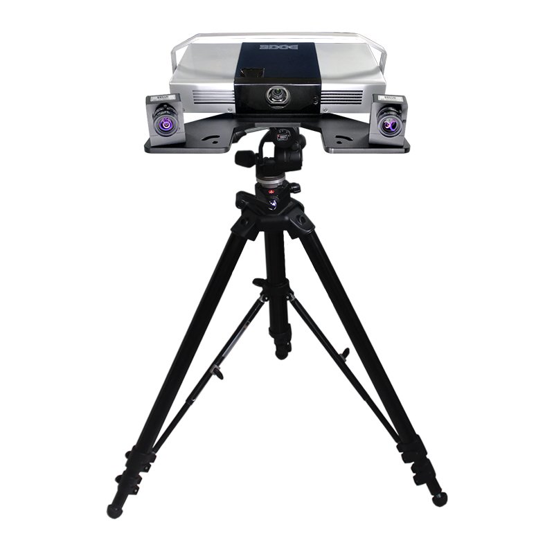
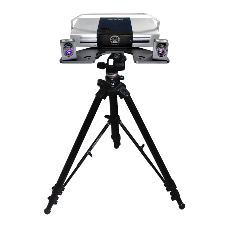
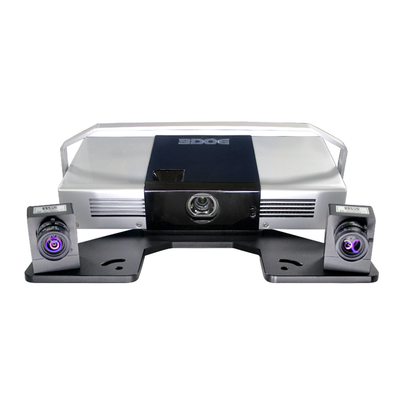
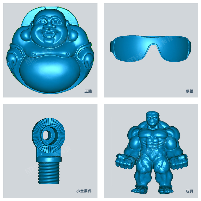
PTS-A series of industrial-grade high-precision 3d scanning photo is suitable for industrial design, reverse engineering and dimensional 3D detection, non-contact structural optical measurement, camera imported from Germany, independent research and development of supporting software, with high precision and stability. Successful solutions are applied in the following fields: reverse 3D scanning and 3D detection of molds, sheet metal parts, large-scale casting parts, oil-clay models, injection parts, sculpting parts, auto parts, etc.
PTS-A series of industrial-grade high-precision 3d scanning photo is suitable for industrial design, reverse engineering and dimensional 3D detection, non-contact structural optical measurement, camera imported from Germany, independent research and development of supporting software, with high precision and stability.
Successful solutions are applied in the following fields: reverse 3D scanning and 3D detection of molds, sheet metal parts, large-scale casting parts, oil-clay models, injection parts, sculpting parts, auto parts, etc.
Photographic 3D scanner-measurement principle
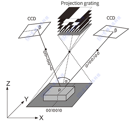
The 3DOE 3D measuring head is composed of two high-resolution industrial CCD cameras on the left and right and a grating projection unit. The structured light measurement method is used to project a group of grating fringes with phase information onto the surface of the measured object using the grating projection unit. The two cameras on the left and right can measure simultaneously, and combine computer vision technology, photoelectric sensor technology, image processing technology and software control technology to obtain high-density three-dimensional data on the surface of the object in a very short time. The rotating object or scanning head is used to change the scanning angle of view. Based on the automatic splicing technology of multi-view point cloud, it can complete 360° scanning of the object in all directions.
Product Features:
hardware
1) German imported industrial-grade high-precision camera, single scan dots (pixels): 1.3 million x2.
2) The lens position and scanning distance can be flexibly adjusted to achieve a variety of scanning ranges and accuracy, suitable for scanning products with different sizes as small as a few millimeters to several meters.
3) Non-contact (white light) raster projection scanning technology is suitable for the measurement requirements of soft and easily deformable objects.
4) The equipment hardware is small in size, occupies a small area, no noise, and can be easily brought to the measurement site.
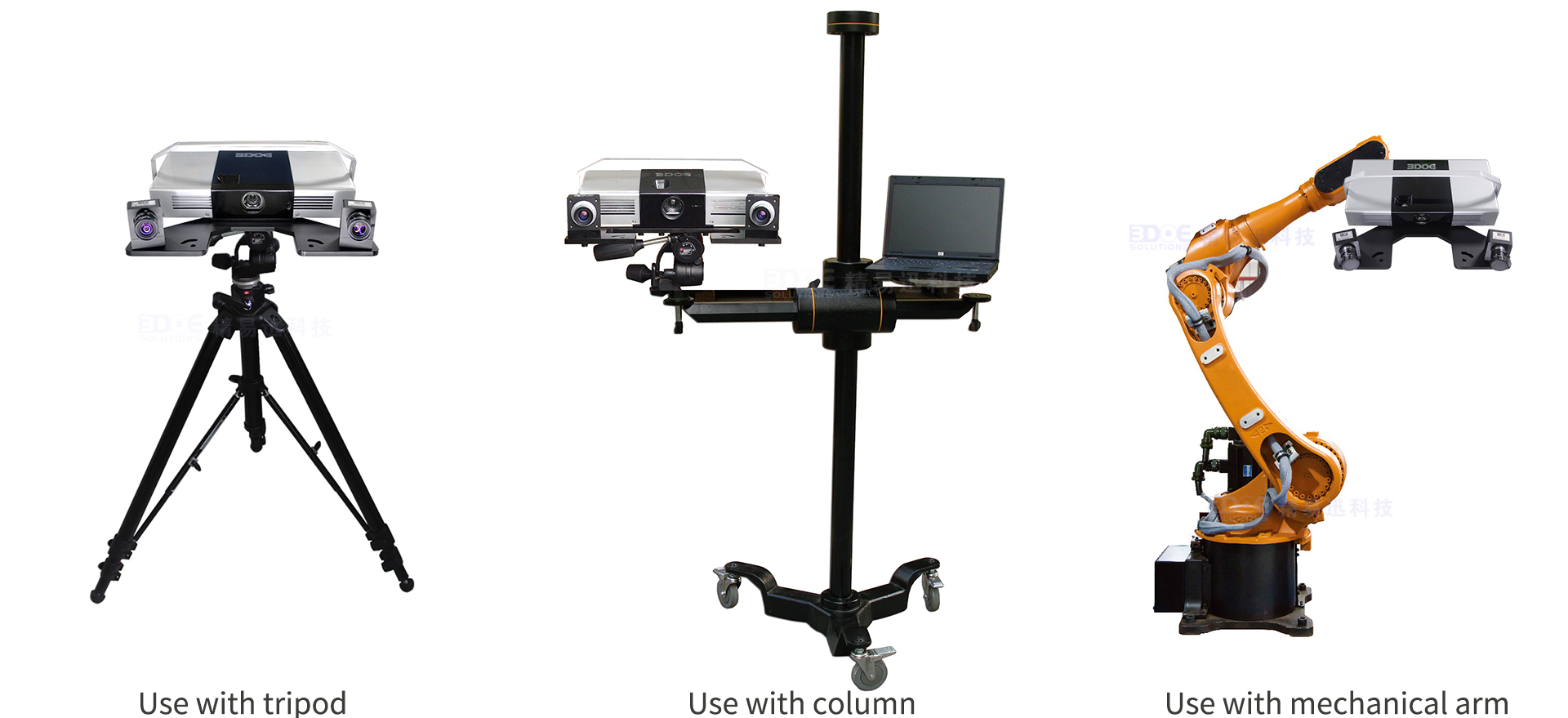
5) It can be used with a tripod, robotic arm, and turntable to flexibly adjust the position of the scanner to suit the scanning of heavy and difficult-to-move objects.
software
1) Automatic splicing of marker points, intelligent fusion into a single-layer point cloud, to form three-dimensional object measurement data, so as to achieve all-round scanning of the object.
2) Independent R&D and manufacturing, independent software intellectual property rights, professional R&D team, provide 24-hour machine service, which can be customized according to customer needs.
3) The scanning operation is simple, and it can be operated proficiently without excessive training (2-3 working days);
4) The measured point cloud data is ASC, STL, PLY, IGES, OBJ, DXF, etc., which can be directly exchanged with Surfacer, image ware, UG, CATIA, Geomagic, Pro/E, Master CAM and other software.
Optional accessories
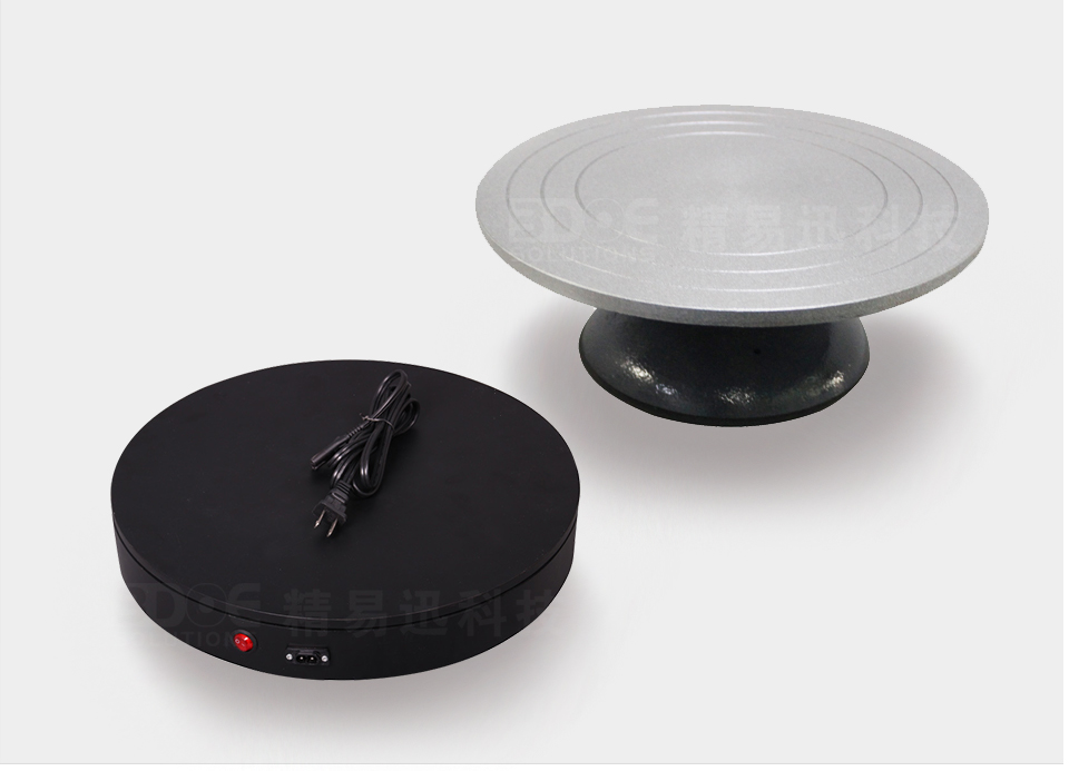
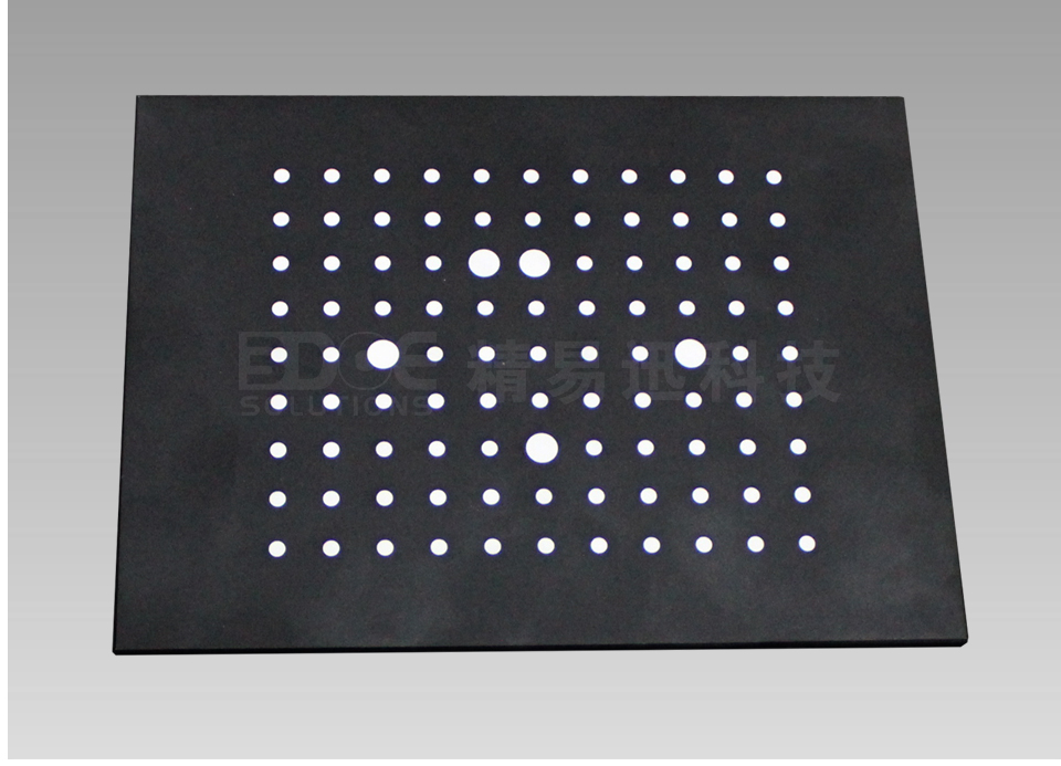
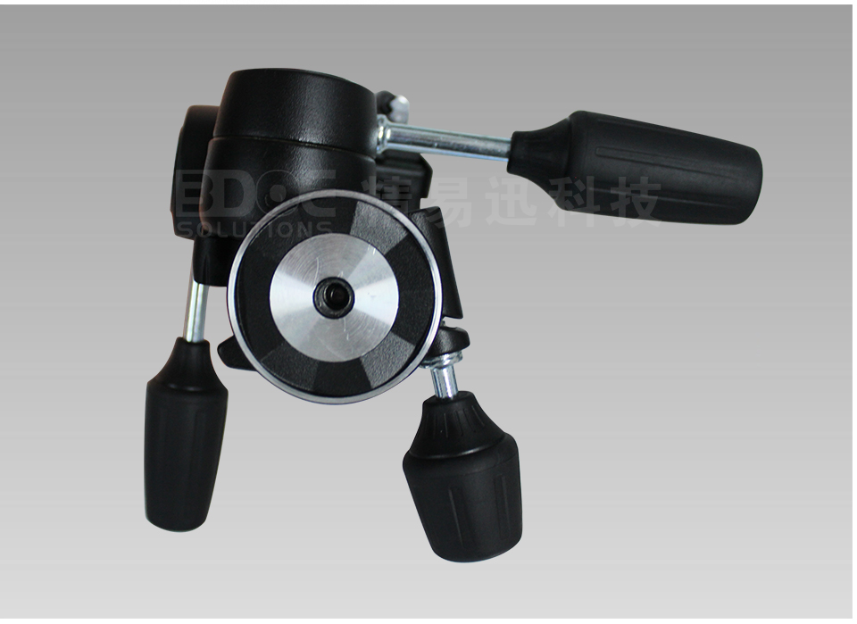
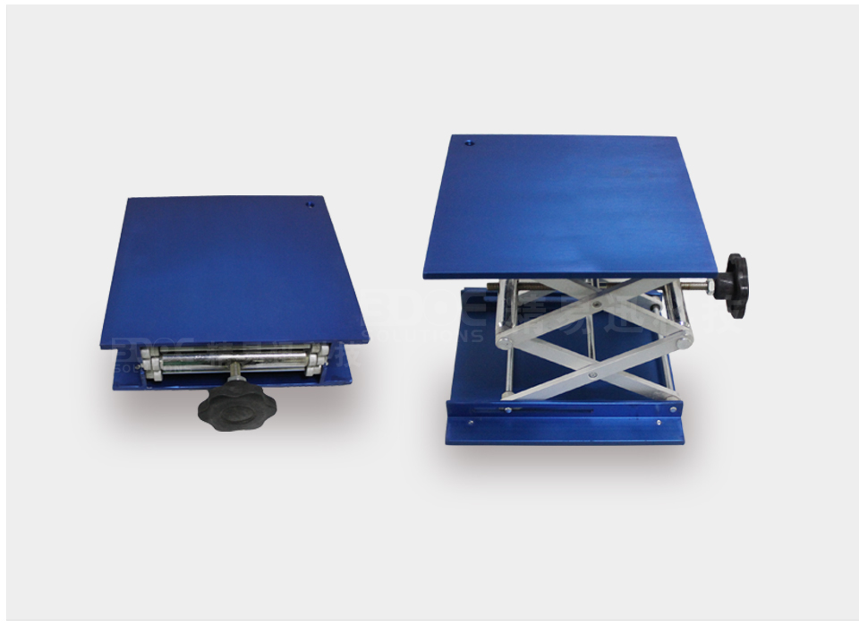
Automatic/manual turntable Calibration board Steering head Lifts
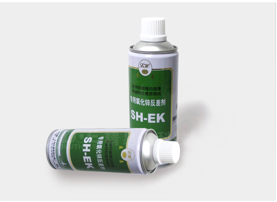
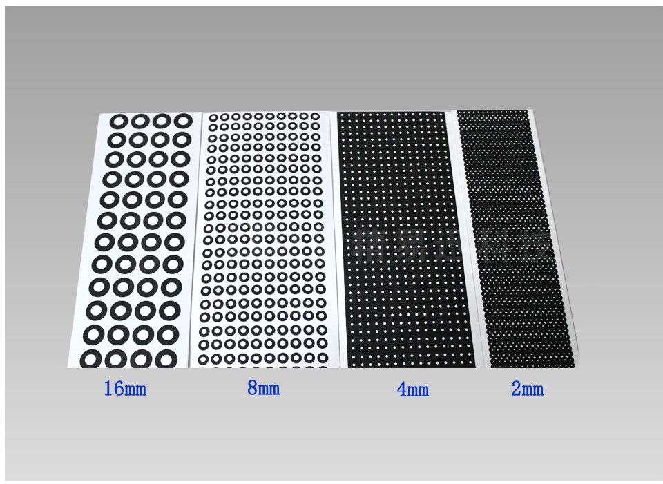
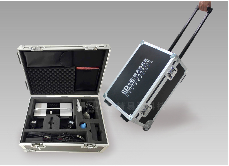

Developer Mark point Flight Case Tripod/Column
▣ Classic cases
Precision metal parts size inspection
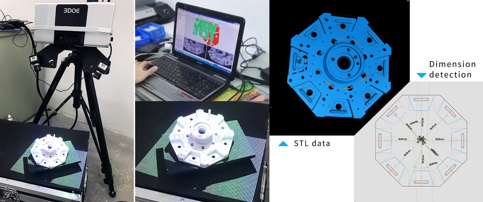
Reverse Design of Glasses 3D Scanning

Scan for STL data 3D modeling or extraction of feature boundary lines
▣ Technical Parameters
Number of lenses | Binocular type | |
Product number | PTS-A130 | PTS-A130-SO |
scanning method | Non-contact white light scanning | |
Single scan range (mm2) | 100×75~400×300 | 50X40~200 X150 |
Maximum measuring range (mm3) | 2000×1500×1500 | 1000 X750 X750 |
Measuring accuracy (mm) | 0.02~0.05 | 0.015~0.05 |
Single scan points (pixels) | 1,300,000×2 | |
Single scan speed | <5S | |
Average dot pitch (mm) | 0.07 ~ 0.3 | 0.04 ~ 0.15 |
Output file format | ASC, STL, OBJ, etc., can be connected with Geomagic, Imageware, 3Dmax, etc. | |
Splicing method | Automatic splicing of marked points, intelligent fusion into a single layer point cloud | |
▣ Application field
●Auto parts
Mould

Sculpture
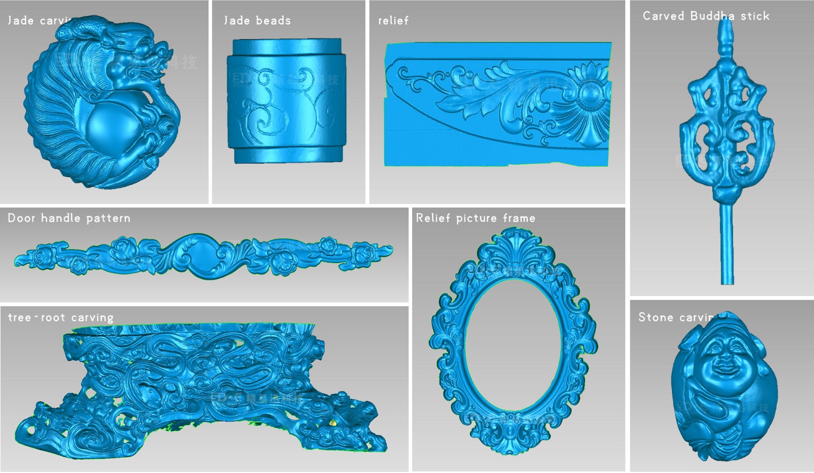
Bathroom

Toy figure

Small parts
3D printing
Reverse Engineering……
To understand the specific application, please feel free to consult online (message) or call 0755-86131192!
Provide system customized solutions!